I decided that I would write a more detailed article about the rendering module of the Trixels engine. Many things changed implementation-wise since last year, and I feel that now is a good time to go public as it’s probably not going to change much anymore.
I really don’t mind “coming clean” about how things are done, since Fez certainly didn’t invent non-interpolated orthographic voxels or whatever you might call trixels in a more formal language. Trixels are just a technology support for Fez’s art style, not necessarily the best, but one that works and that I’d like to share.
You should probably check the first post I made about trixels to get the basic idea first.
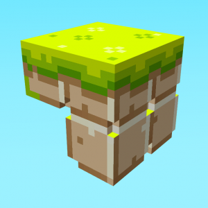
Here’s the trile I’ll dissect for this post, in a perspective view :
Memory representation
Each trile at its creation is a full 16³ cube, without any holes. The editing process consists of carving trixels out of the full shape to get a more detailed object.
The very first version of Fez recorded all the trixels that are present inside a trile, which means an untouched trile would contain a list of all the possible positions inside the trile to say that these positions are filled.
It became obvious early on that most triles have a lot more matter than holes, so the second version recorded the missing trixels instead. But even that became hardly manageable, especially in the text-format/human readable intermediate trileset description files; they were still too immense to edit by hand if needed, and took a while to parse and load because of their size. The memory usage was questionably high too for the little data that was represented.
I tried using octrees, but that kinda failed too. Thankfully Saint on the tigsource forums gave me a better idea; to use missing trixel boxes, so the smallest amount of the largest possible missing trixels cuboids. The good thing about these is that a box is represented by a 3D vector for its size and a 3D point for its position, that’s it!
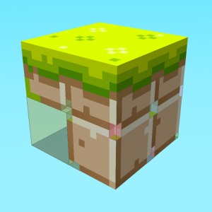
Here’s a visualization of what these boxes looks like. Adjacent boxes have the same color.
The editor tries to keep these boxes as big as possible and their number as small as possible in realtime while you edit, but my algorithms aren’t perfect yet. A “best effort” scenario is fine though, a couple of superfluous boxes have little effect on memory usage/file size.
Polygonization
The rendering strategy of Fez is to draw the bounding surfaces of each trile as a triangle list and ignore everything that’s inside a trile. To do that, we must first isolate the contiguous surfaces of the trile, and then split it in triangles.
To extract surfaces, I assume that all of the actions from the initial filled trile are incremental. By that I mean that all you can do in Fezzer when sculpting a trile is remove a trixel or add a trixel, and each of these operation creates, destroys or invalidates surfaces; but each is treated separately and acts on the current state.
…I was going to explain the algorithm in detail, but I feel like it’d be just confusing and unnecessary. So, exercise to the reader. :)
Whenever a surface is modified/created, another pass tries to find the smallest amount of the biggest possible rectangles inside that surface. It’s the same thing as with the missing trixel boxes, but in 2D this time (also alot easier to do right!). My algorithm traverses the surface from its center in an outward spiral and marks all the cells that form a rectangle; the remaining cells are traversed later, recursively until the whole surface is covered with rectangles.
Each rectangle is then a quad that is formed of two triangles, which we can render directly. A vertex pool makes sure that there are no duplicate vertices, and maps the indices appropriately.
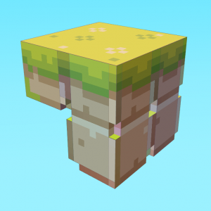
Below is a visualization of the rectangular surface parts of the same trile, in filled geometry mode and in wireframe.
Mass rendering
So that’s a single trile. A level is formed of a ton of triles, we don’t want to draw everything at all times. How do we manage that?
And rendering a lot of small objects in sequence is not very GPU-friendly, so how do we group batches efficiently?
The answer to the first question is efficient culling. Since the world is in essence formed of grid-aligned tiles, it’s easy to find which are visible in the screen or not, and render selectively. But Fez also works in the third dimension, and the depth range can be really big, so we need to find which triles we can skip rendering if they’re behind another trile. Simple enough, traverse to the first visible trile for each screen-space tile, and render this one only. But some triles can be flagged as see-through and let the traversing continue until we hit a non-seethrough trile or the level’s boundaries.
For tilted isometric views, a similar culling algorithm is used, where we try to find the triles with no neighbours on the faces that the camera can see. In perspective view, it’s a lot harder to cull without occlusion queries, which I didn’t want to get into… But 99% of the game is played from an isometric perspective so it’s no big deal.
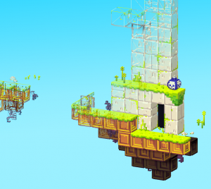
Here’s a scene from the GDC ’09 trailer in a 2D view that you’d play in, and how it’s culled. The world extends in the third dimension, but we only need to see its shell!
The second thing is batching.
In the very first XNA version of Fez, I tried to call DrawUserIndexedPrimitives repeatedly for each trile in the world and hope for the best. It was unplayable, because as it turns out there is considerable overhead to draw calls and doing fewer, bigger draw calls is the key to 3D performance.
Each level has a trile set that contains a restricted number of different trile templates, and the level indexes integer 3D grid positions with elements of that trile set. Trile instances have a very limited set of properties to themselves (like rotation and offset) but every instance of a template trile shares geometry, texture and collision information. So I felt that geometry instancing was the way to go for batch rendering.
Different hardware supports different flavours of instancing but shader instancing is the common baseline for all Shader Model 2 and above GPUs, so I went with that. My current implementation of SM2 instancing supports 237 instances per batch, and the instance information is stored as vertex shader constants. The number will probably go down if I need to add more information to individual instances, it’s really minimalistic right now. But I found instancing to provide excellent performance on older hardware, current-gen GPUs and consoles, and not too hard to get to work well.
That’s it! Hope you enjoyed the tour. :)
Any questions?



Hey, I love hearing semi-technical walkthroughs on development like this, thanks a lot for posting! I’d like to do some 3d work someday, but it is a bit intimidating.
Very cool article, thanks for the extra insight. I love the idea of making a game with a solid set of tools and tech behind it.
I don’t get it. First you state that you wanted to change the structure and files so they were readable and editable by hand if needed. But then he comes up with the missing box algorithm.
Which is even harder to edit by hand (because now you need to calculate yourself which areas aren’t visible).
Why didn’t you just saved the polygon (quad) strip ? it would be easy to calculate which voxels are used within the editor from the polygon strip. And it’s all you need to render the scene ingame.
@Hugo
I never really had to edit the voxel data by hand in the files. I mostly want to keep the files to a manageable size so that I can edit the other trile metadata like collision, and actor/event stuff.
Reconstructing the voxel data from a list of quads that doesn’t necessarily form a convex hull sounds really complicated to me. The boxes were just a simplification of storing the voxels as an array, and it works on top of the existing code without too much effort…
Also I should mention that the game and the editor don’t access the same content files. The editor compiles game-format content that does not contain voxel information, only polygons.
Hi, are there any possible way to get a copy of the fezzer? I am a huge fan and would love to play around with it!!!
Thanks
Not for the moment :)
It would be very hard to use because FEZ wasn’t meant to be extensible. But in a few years, as a toy, perhaps!
Well, I think it wouldn’t be too hard. And it would suit all your needs (be readable and small). And it adds the benefit of being able to use the same data in the editor and game.
I’m not claiming that what I propose is a best/better way. Your approach seems to work just fine.
I just recently finished work on my own voxel engine for NDS (you can see more about it on my website). And because of the limitation of the DS I had to think hard about subjects like data storage. Because of this I’m quite curious to see how others solved their problems :)
So the trixels are only used during the modelling of each Trile, and all the engine sees is a set of triangles for each Trile? Does this mean that in theory it would have been possible to model and texture the Triles in an existing modeller, such as 3DS Max?
Surely that would have been les work than creating the voxel modeller and coming up with the triangulation algorithm?
Yes, we could’ve used an external editor, maybe even make extensions for Blender or another modeling package instead of building from scratch. Building the content in our own editor was a decision that was taken very early on, with the intent of making map edition as easy as possible, so we carried on with it…
In retrospect it was a lot of work (and still is), but the modeler is truly made for trile edition and so it’s very smooth to work with. Having complete control over the content, tools and geometry also feels like a plus.
By the way, both of you work on really impressive stuff. I learned about the Thermite3D engine very recently, and it’s amazing to see in action. A voxel engine on the DS is quite a feat too!
Yeah, I can see it wouldn’t be trivial in 3DS Max. You’d probably still have to buld the Trile out of cubes, and then have 3DS Max handle the merging.
I’m keeping an eye on your project anyway, you’re doing good things for the name of voxels/trixels ;-)
Further discussion of this post on a voxel related forum: http://www.jonof.id.au/forum/index.php?topic=1683.0
Very informative, I was wondering how trixels weren’t just some fancy name phil made for voxels.
so, why would anyone ever use voxels again ever?
Very nice looking result you have there. Trixels seem to be 16^3 cuberilles,
so it’s actually more like the name for the tiles in the trixel engine, right?
Perhaps polygonizing voxel data is not as bad as it seems, you make it look good.
-How would your method treat a 3d-checkerboard patterned trixel?
Would it triangulate just the outside surface?
Keep it up! Looks great!
Actually, the 16^3 tiles are called Triles in the engine, and the individual atoms/voxels are the Trixels. What makes it all confusing is that the engine itself is also called “Trixels”… :P
Polygonization of triles is independant from coloring/texturing, because it’s done via a cubemap afterwards. So if a checkerboard trile has no extra geometrical detail, it’ll be polygonized as a flat 6-face cube.
Hello, I was wondering if you would be able to share a more detailed description on the algorithm used to create the rectangles. I’d love to try an implementation of this myself but I’m not sure on how to start. Thank you.
I’d share the code, but it’s an entangled mess… I’d have to share the whole engine for it to make sense.
So basically :
I start with a surface, which is an array of 2D positions. It doesn’t have to be rectangular, or convex, but it has to be contiguous.
Find its center.
Make sure the center corresponds to a filled cell (i.e. not a hole), if it’s a hole, spiral around the center and find the nearest filled cell.
Spiral around the current cell to find the closest “wall” (empty cell) to the biggest possible rectangle originating from that point. (http://2000clicks.com/MathHelp/SquareSpiral.gif)
After hitting a hole, propagate to the three other directions to find the other borders. This is a not a spiral traversal, but just running along the edge and expanding until you find a hole.
Then subtract all the cells you tagged from the surface, and start over until there’s no cell left.
Hope it helped! :)
Interesting stuff!
Is there no way this can be done in the shader though ? I don’t mean the VS as this would mean a lot of needless triangles in a trile, but in the PS itself:
Where a cubemap holds both colour AND depth information for each 16×16 side of the trile… and the shader performs the offsetting of each trixel, based on X, Y and depth from surface – with, of course, reference to a bound depth buffer.
I’m new to shaders but I’ve got an strange feeling that this could be done, having seen some incredible things done in the PS. However I don’t yet know enough to qualify my assumption so I could be wrong – hell, probably am : )
Nice work though, I am about to go see if I can implement an efficient routine for creating optimum dynamic meshes for a trile while adding and removing trixels at runtime. Sounds like a very head-stretching activity, which I love. Beats sudoku : )
-Gary
Hiya Gary,
The closest way of doing actual displacement in a pixel shader is via Parallax Mapping (doesn’t handle silhouettes) or Relief Maping (can handle silhouettes).
Parallax mapping only gives an impression of depth and doesn’t handle every view direction well, so for square shapes it’s less than idea.
Relief is pretty convincing, but it is SLOW when it’s accurate. It’s basically ray-casting in the pixel shader, with texture lookups in a loop. I’m 99% sure that using actual polygons is faster, especially in my case where shapes are blocky and easily triangulated. Relief/Parallax is good when your shapes are organic and smooth.
See : http://forum.unity3d.com/threads/32451-Fabio-Policarpo-Relief-Mapping-with-Correct-Silhouettes
Hi, (now i can comment this)
By reading again this article, i understand the all modeling part but not the texturing part.
How do you texturing this kind of custom mesh ? What kind of shader ? (i’m a little bit confused)
BTW, i really like the way you write this post. :)
Hi!
The texturing is done using a cubemap (which is flattened to a 2D texture, but it’s still 6 square faces), and the texture coordinates are generated such that each polygon will sample the face into which the normal points, without paying attention to depth.
It’s kinda hard to put into words… but the shader itself is very simple, standard tex2D lookup. The “hard part” is generating the texture coordinates when building the mesh.